Project name: PolFEL – Polish Free Electron Laser (phase 1.0)
Project implemented under Action 4.2 of the Intelligent Development Programme 2014-2020, co-financed by the European Regional Development Fund
Project implemented by a consortium comprising:
National Centre for Nuclear Research - consortium leader
Military Academy of Technology
Warsaw University of Technology
Łódź University of Technology
Wrocław University of Technology
University of Zielona Góra
University of Białystok
Jagiellonian University
Project goals:
Direct project objective:The direct objective of the PolFEL project, which is included in the Polish Research Infrastructure Roadmap, is to create a modern research infrastructure - in line with the country's strategic development directions - in Area 2. Development of science through interdisciplinary research.
Interim project objectives:
Achieving the direct objective of the project will enable the achievement of the intermediate objectives:
Creation of a target of 16 new scientific posts within the established PolFEL research infrastructure
Use of the PolFEL infrastructure for the purposes of business activity, both by external stakeholders (entrepreneurs, research centres, etc.) - in the amount of at least 40% of the equipment working time, as well as their own (including commercialisation of the results of research and development works conducted).
Carrying out research and development work in the broadly defined area of physics, chemistry, molecular biology, medicine, technology and materials research, both for own use and for commissioning by external stakeholders, including entrepreneurs, within the framework of the economic use of infrastructure (research services and contract research).
Project description:
Undertaking work on the construction of the free-electron laser makes it possible not only to provide Polish scientists with a modern device that can be used in many areas of science and technology, but also to become involved in European programmes. Thanks to this project, Poland emphasises its importance on the map of large research installations in Europe. It is worth noting that the construction of PolFEL is not in competition with the Kraków synchrotron project. These two sources emit radiation with completely different characteristics and are complementary devices.
The PolFEL Polish free-electron laser project prepared by a consortium of eight research units will receive funding from the Inteligent Development Operational Programme. The decision to allocate more than PLN 118 million for this purpose has reached NCBJ, where the new research device will be developed. The Polish project will be supported both scientifically and technically, thanks to, among others, NCBJ's cooperation with the creators of the world's most powerful device of this type, which has been operating for a year in Hamburg.
Free-electron lasers, of which there are already several dozen in the world, make it possible to study materials, chemical molecules, biological molecules and the dynamics of processes in which they participate with a precision unavailable with other methods. The results of research using these devices may have revolutionary significance for medicine, chemistry or electronics.
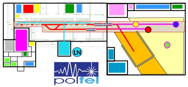
"We have an ambitious plan to build the PolFEL in the next four years". - explains Dr Paweł Krawczyk (NCBJ), who is leading the project. "In the design of our free-electron laser, four essential elements can be distinguished. The first is an electron source equipped with a superconducting photocathode. Next are four superconducting cryomodules that accelerate electrons to energies reaching a maximum of 180 MeV. Two undulators will be placed in the path of the accelerated electron beams, in which the electrons will move slalom in a non-uniform, specially shaped magnetic field. During the forced oscillatory motion, laser action will take place and the electrons will emit photons arranged in extremely short but intense pulses of coherent electromagnetic radiation, i.e. light. At the end of the system there will be three experimental stations to which the photon beams will be derived and one using an electron beam. " The PolFEL will be able to produce light with a wavelength of more than 100 nanometres, thus covering part of the ultraviolet range. Researchers will also have longer wavelength radiation available, including terahertz and infrared radiation. "We plan for PolFEL to operate not only in pulsed mode - like all existing free-electron lasers to date - but also in continuous-wave mode, in which pulses of radiation are generated at a constant frequency," adds Dr Krawczyk. "This will make it possible to study some rare processes that escape the methods used so far."
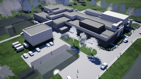
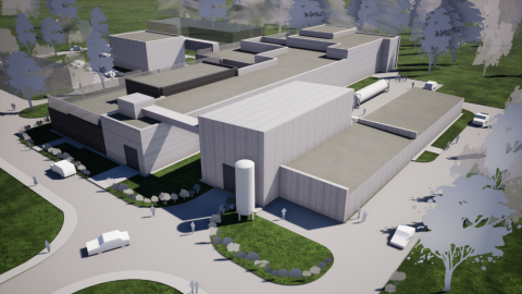
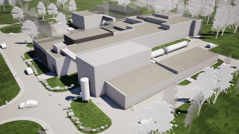
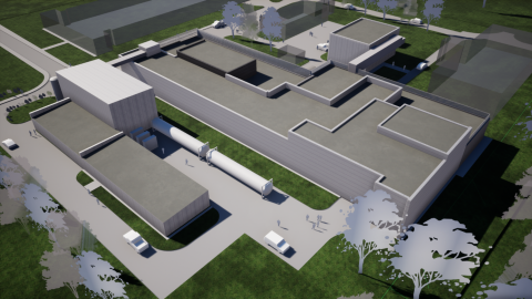
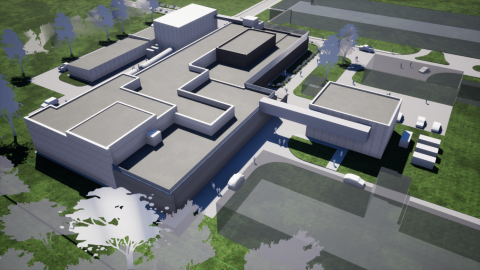
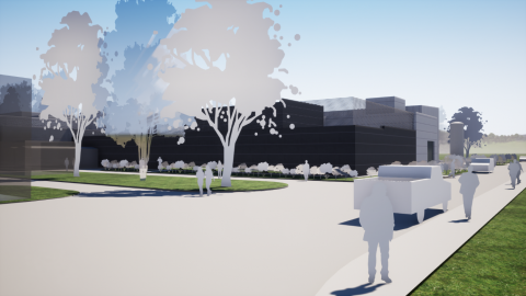
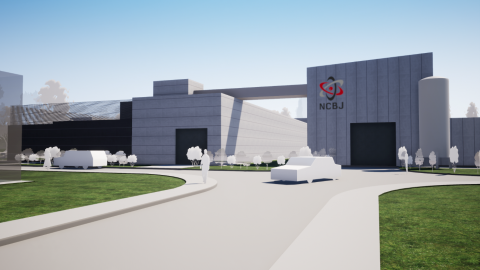
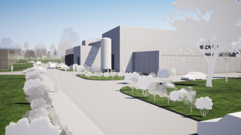
PolFEL will be built in the rebuilt historic hall of the first Andrzej proton accelerator built in Świerk. A new hall will be built next to it to house the research stations. Rooms for the new superconducting photocathode laboratory will be added to the Andrzej hall.
The project will be possible thanks to the extensive experience gained by Polish scientists and engineers during the construction of the XFEL laser in Hamburg. NCBJ is a co-shareholder in the international company that owns it, and in addition to NCBJ, other Polish institutions including IFJ PAN and Wrocław Technology Park also participated in the construction of the laser.
NCBJ's fruitful partnership with the laboratory in Germany continues. On 25 June, an addendum to the cooperation agreement between NCBJ and European XFEL GmbH was signed. The existing agreement provided for cooperation in the processing of data collected by experiments conducted in Hamburg. The annex expands the field of cooperation in data processing and adds joint work on free-electron laser technologies, as well as planning NCBJ's participation in the preparation of a concept for the use of two of the five tunnels that lead particle beams out of the XFEL accelerator. "The XFEL consortium is interested, among other things, in the work on lead superconducting photocathodes that we have been conducting for several years," explains NCBJ director Prof Krzysztof Kurek. "The photocathodes under development are intended to enable free-electron lasers to operate in continuous wave mode or in long pulse mode. We also want to use such cathodes in the laser to be built in Świerk. " NCBJ scientists also report a concept of using a novel method to obtain monoenergetic gamma photon beams in one of the XFEL channels. Such photons would be created by colliding electrons coming from a laser accelerator with a photon beam emitted by a conventional laser. This concept is also to be implemented in the PolFEL project.
The PolFEL laboratory, which will be established at NCBJ, will be co-created by the hosts and specialists from the Military University of Technology, Warsaw University of Technology, Łódź University of Technology, Wrocław University of Technology, University of Zielona Góra, University of Białystok and Jagiellonian University. The Polish researchers will be supported by NCBJ partners - including DESY laboratories, STFC Lab Daresbury, as well as European XFEL GmbH and the companies RI Research Instruments GmbH and Kubara Lamina S A. Most of the funding will come from the Intelligent Development Operational Programme established by the European Union. The Programme's implementing body intermediating in the funding process is the Information Processing Centre (OPI) - National Research Institute.
Additional information:
More on the laser parameters:
The PolFEL laser accelerator will operate in continuous wave (cw) and long pulse (lp) modes. Electrons will be accelerated by four cryomodules, accommodating a total of eight TESLA SRF cavities. The 120 MeV and 160 MeV energy beams in cw and lp mode will be directed to the VUV undulator, while the lower energy beams will drive the THz undulator. The generated radiation in the range of 0.3 mm to 150 nm for the first harmonic (50 nm for the third harmonic) will be delivered for experiments performed in a dedicated experimental room. The expected pulse energy will be at the level of 100 μJ for VUV and tens of microjoules for THz radiation. The maximum photon flash frequency of the beam will be 100 kHz. The electron beam, after passing through the VUV undulator, will be secondarily used to generate neutrons or will be used for Compton backscattering. Part of the unit's operating time will be devoted to research into the development of FEL technology and new accelerator components in collaboration with STFC Daresbury, E-XFEL and DESY.
UV pulsed laser (or with UV harmonic generation module) for photocathode cleaning
Auxiliary high repetition rate femto/picosecond pulsed laser system (to an existing laser system not manufactured as part of the project) to ensure continuous operation of the electron source
Harmonic generation systems (second and fourth harmonics) for high repetition rate femto/picosecond laser systems (existing and auxiliary)
Beam guiding and shaping systems
Optical system to guide the beam from the laser to the electron source
Optical system shaping the laser beam for optimum electron packet emission
Optical table with vibration stabilisation
Laser beam diagnostics systems
Beam power and pulse energy meters
Beam position meters
Beam cross section power/energy distribution meters
Laser pulse width over time meters
Spectrometers to study the spectrum of laser light
Optical table with vibration stabilisation
Optical system in the diagnostic section with optical path that the laser beam has to travel to the electron source
Other systems (high-speed cameras, etc.) for laser pulse diagnosis
Support systems
Anti-vibration system to minimise vibrations in the laser optical path
Covers for the beam guiding/shaping system and diagnostic system
Remote control systems for the laser beam and its parameters as well as optical and opto-mechanical components
Technical infrastructure components
High-temperature heat stabilisation system connections (water)
Connections for technical gas distribution systems
Supports and positioning systems
System cabling
Flow sensors, pressure sensors, temperature sensors
- the superconducting resonance cavity of the launcher,
- lines and connections of the liquid He cooling circuit,
- superconducting solenoid
- Transmission window and optical path of the laser excitation photocathode
- HF coupler
Beam collimation and diverting systems
Electro-optical packet profile monitor(denser)
Beam current transformer
2 XY correctors
Vacuum equipment
Pump systems for high vacuum
Ion pumps
Cryogenic pump
Connection pieces for UHV vacuum
Pneumatic shut-off valves
Manual shut-off valves
BPM-type beam monitors
"YAG Screen Chamber" type beam monitors
Microwave equipment
HF amplifier 1300 MHz, power=2500W
Waveguides
Circulator + water loads
Directional couplers
Microwave detectors
Technical infrastructure components
High-temperature heat stabilisation system connections (water)
Low-temperature heat-stabilisation system connections (helium)
Connections for technical gas distribution systems
Supports and positioning systems
System cabling
Flow sensors, pressure sensors, temperature sensors, measuring probes
Class 1000 clean room for photocathode pretreatment including ancillary equipment
Cleanroom and/or tent of class 10/100 for fine preparation of photocathodes including ancillary equipment
2 undulators with variable gap width, on permanent magnets:
- with a magnetic structure length of 8 m and a period of 2 cm,
- with a magnetic structure length of 4 m and a period of 5 cm,
Each undulator consists of a steel frame, two aluminium beams supported on it and brackets attached to hold several hundred blocks of permanent magnets, a system of bolts, motors and gears that ensure the movement of the beams, an encoder system of position sensors, a control system.
Beam collectors
Beam collimation and diverting systems
Electron optics system (air-cooled electromagnets): 8 dipoles, 10 small correction dipoles, 15 quadrupoles.
- Experimental chamber with environmental sensors to maintain very low humidity
- Optical table with vibration stabilisation
THz photon beam splitting system for test stands
Arrangement for guiding the THz beam in a very low humidity atmosphere (tubes)
Optics kits (lenses, mirrors, filters, beam splitters, etc.) and optomechanics (mounts, manual and motorised sliding tables, etc.) for beam experiments
Pump-probe spectroscopy system
Optical systems combining an optical laser beam and a THz beam
Electronic control system
Detector system
Optics and opto-mechanics systems
Delay lines
Laser beam diagnostic systems
THz beam generating/receiving antennas with all supporting systems (Lock-in amplifier, power supplies, etc.)
Sample holder for transmission and reflection tests with accessories (cuvettes for liquid and gas samples, magnetic stirrer, etc.) for testing various materials
Equipment
Power and/or energy meters (min 3)
High-speed radiation detectors (min 3 pcs)
THz camera for direct beam visualisation
Thermal imaging camera for indirect beam visualisation
2D beam scanner and angle scanner
Cryostat
Temperature module
FTIR spectrometer
ATR prism
Two lock-in systems including choppers
Sample heating system
Cuvettes for liquids and gases
Pasteuriser for solid samples
4 National Instruments PXI stations including control systems
4 LabView stations
Polarisation optical microscope with accessories (heating/cooling table, CCD camera, etc.)
Raman spectrometer
Technical infrastructure components
Low-temperature heat stabilisation system connections
High-temperature heat stabilisation system connections (water)
Technical gas distribution system connections
Supports and positioning systems
System cabling
Flow sensors, pressure sensors, temperature sensors, filters
High-frequency signal monitors - Leakage in the microwave power distribution system
Detectors of gases used in the installation, in particular He (leakage in the cryogenic system)
Fire protection system
Personnel Protection System (PPS):
Main components
Access control system to deactivate the accelerator if a person is detected in a prohibited area (accelerator tunnel during operation), e.g. by opening the door.
Visual and acoustic signalling system informing about the current status of the machine and the actions carried out (e.g. accelerator start-up)
Voice communication system (intercom, wireless communication)
Building (annex to hall 5) of the electron source laboratory (photocathode research, laser and office space)
Hall 5, where the accelerator will be installed (own in-kind contribution to the project)
Acceleration cryomodule
International Test Cryomodule, 2 x 7 cavities - obtained independently from the project as part of a scientific collaboration with STFC, used for testing and development work or interchangeably with one of the 2x9 cavity cryomodules
Optical equipment
LOTIS nanosecond laser
High repetition rate femto/picosecond pulsed laser system (under selection and purchase procedure) generating an infrared beam:
- with a second and fourth harmonic generation module
- with other subsystems such as the Optical Parametric Amplifier, allowing wavelength tuning from ultraviolet to visible light
Support systems
Optical table system.
Laser beam diagnostic systems in the laser laboratory
Connection for cooling the photocathode to liquid He temperature
Vacuum equipment
Vacuum chamber for photocathode testing
Diagnostic systems in the vacuum chamber for photocathode testing (Auger spectrometer, dark current test system, photocathode emission current measurement system)
Vacuum diagnostic systems
Pump system for high vacuum (turbo pump, scroll pump)
Ion pump
Technical infrastructure components
Low-temperature heat stabilisation system connections (helium)
High-temperature heat stabilisation system connections (water)
Connections for technical gas distribution systems
Supports and positioning systems
System cabling
Flow sensors, pressure sensors, temperature sensors
Class 10000 clean room for laser operation and photocathode test stand with temperature stabilisation system


